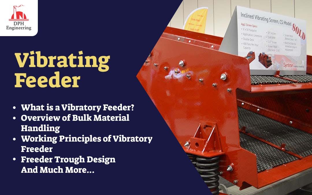
Introduction
This blog covers everything you need to know about vibratory feeders.
Read further to learn more about:
- What is a Vibratory Feeder?
- Overview of Bulk Material Handling
- Working principles of Vibratory Feeders
- Feeder Trough Design
- And much more…
Chapter 1: What is a Vibratory Feeder?
A vibratory feeder is a system for moving parts or materials into an assembly process. It uses controlled vibrational forces, gravity, and guiding mechanisms to place and orient the parts or materials. They have different widths, lengths, and depths of accumulation tracks that are carefully chosen to meet the needs of the application, material, component, or part.
Vibratory feeders are used to moving, feed, and transport bulk materials by using different types of vibrations to get the materials in the right position to be added to a production line. They are a very effective way to speed up assembly work and gently separate large amounts of materials. A vibratory feeder moves things in a straight line by using horizontal and vertical accelerations to make the right amount of force to move things into place.
The linear or gravity accumulation track of a vibratory feeder slows down the vibrations and helps the feeder move in the right direction. The vibrations, rotation, and force can come from piezoelectric, electromagnetic, or pneumatic motors in the drive units.
A vibratory feeder starts with a transporting trough or platform through which materials are moved by controlled linear vibrations that cause the materials to jump, hop, and toss. Depending on the design, travel speeds can range from a few feet per minute to more than 100 feet (30 m) per minute. This is controlled by the frequency, amplitude, and slope angle.
The different vibratory feeders control material flow in the same way that orifices or valves control fluid flow. They can be set to feed a fixed amount of bulk materials. A structure with soft springs controls vibrations and capacities, which can range from a few pounds of bulk materials per hour to more than several tonnes per hour.
One benefit of vibratory feeders is that they can prevent bridging, which slows down processes and assemblies and keeps materials from moving smoothly. Friction can’t cause a blockage in the throat of a vibratory feeder because the material can move freely through it. There are two types of forces that make flow smooth and even: direct force and indirect force. The immediate force sends force directly to the deck, while the indirect force is a resonant or natural frequency.
Recent vibratory feeder designs have enclosed feeders in a box shape with flanged inlets and outlets. This makes the units dust- or water-tight to prevent spills and make installation easier. Some closed designs use a vibrating bin bottom activator and a vibratory feeder to control flow.
Chapter 2: Overview of Bulk Material Handling
Bulk materials are dry solids that come in powder, granule, or particle form and are a mix of different sizes and densities. Depending on things like temperature, humidity, time, and so on, these materials act in different ways. They don’t move as easily and predictably as liquids and gases. By erosion and impact, they can also easily damage any equipment used to move and handle materials.
When working with bulk materials, it is important to know what they are made of. To make the right bulk handling equipment, these properties must be known.
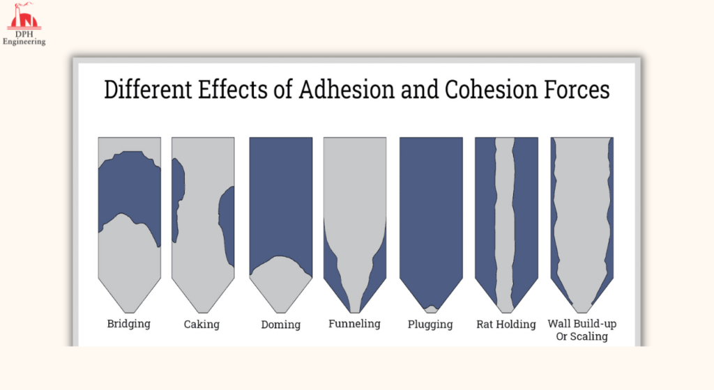
- Adhesion: This is the ability of a material to stick or cling to another material. Gravimetrically discharged materials tend to arc, bridge, cake, etc. while clinging to the surface of the container. This behavior can stop the flow of materials. A debriding mechanism is needed to break up this formation.
- Cohesion: This is a material’s ability to attract or stick to things that have the same chemical makeup. Materials that are very cohesive don’t flow well because they tend to stick together.
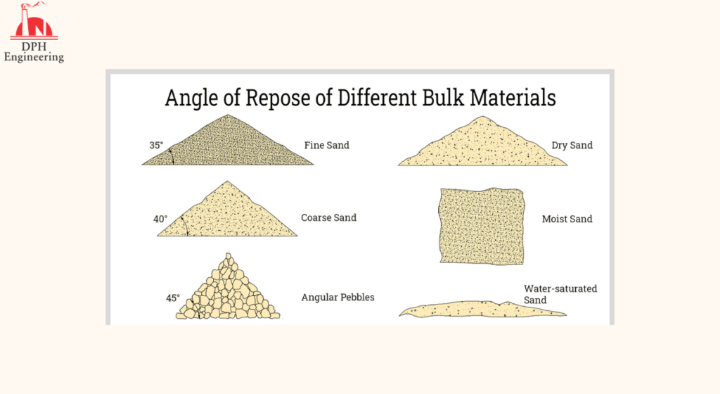
- Angle of Repose: This is the maximum angle between the horizontal and the side of a cone-shaped pile of falling material. This shows how easily a material will flow. The angle of repose is especially helpful when making gravity-powered feeders and conveyors.
- Angle of Fall: This is the angle made by the slope of the cone and the horizontal after finding the angle of repose and applying an outside force to make the cone fall.
- Angle of Difference: This is the difference between the angle of rest and the angle of fall. The more different the angles are, the easier the material is to move.
- Angle of Slide: This is the angle between the horizontal and a flat surface with a certain amount of material on it. This shows how the material moves through hoppers, pipes, chutes, etc.
- Angle of Spatula: This is measured by sticking a spatula into a pile of sample material and lifting it with the most material on it. The angle of the spatula is the average of the angles made by the two sides of the material with the horizontal.
- Compressibility: This is the difference between the packed density and the aerated density in terms of percentage. The size, uniformity, deformability, surface area, cohesion, and amount of water in a material are all affected by its compressibility.
- Bulk Density: This is the material’s weight per unit of volume. Bulk density is important for figuring out the equipment capacity and the compressive strength of the material that can be in the container.
- Particle Size: This is how big a single particle is on average. Most of the time, the equivalent diameter of the particle is used to figure this out. In the table below, you can see how big most bulk materials’ particles are.
| Bulk Material | Typical Size Range |
| Coarse Solid | 5 – 500 mm |
| Granular Solid | 0.3 – 5 mm |
| Coarse Powder | 100 – 300 µm |
| Fine Powder | 10 – 100 µm |
| Superfine Powder | 1 – 10 µm |
| Ultrafine Powder | < 1 µm |
- Moisture Content: Moisture content is the total amount of water in the bulk. Materials with a lot of moisture are harder to work with because the effects of adhesion and cohesion are stronger. Moisture is also a factor in how the weight of the material changes.
- Hygroscopicity: This is how the material acts when it gets wet. Equipment that works with materials that absorb a lot of moisture must be made so that air with a lot of moisture can’t get in..
- Static Charge: Because particles are always touching each other and the walls of the container, they tend to build up static electricity. This is a problem because the forces that hold things together get stronger, making it harder for things to flow.
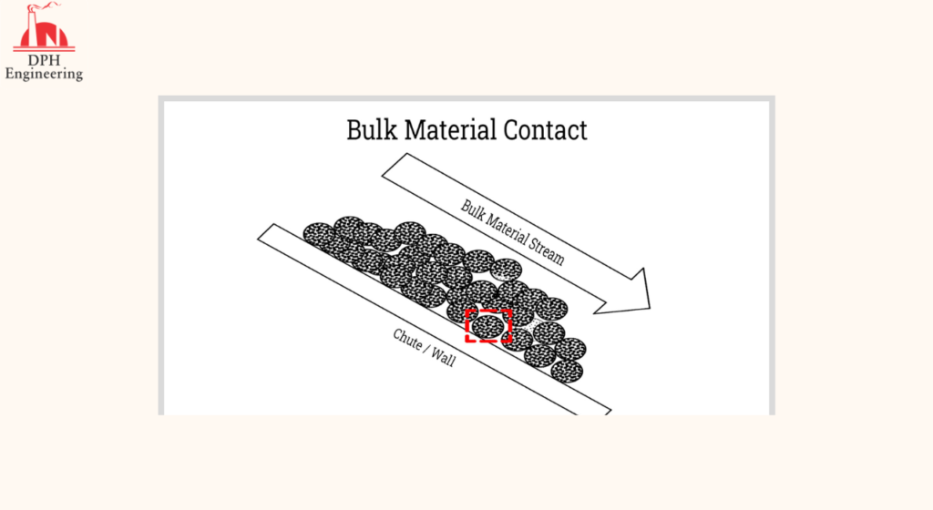
- Abrasion: Abrasion is the material’s ability to scrape or wear down the surface of the equipment used to move it. When moving things like coke and sand, this is a problem. To stop abrasion, hard steels or plastics with high resistance to abrasion are used.
Chapter 3: Working Principles of Vibratory Feeders
A vibratory feeder is usually made up of a drive unit that makes the vibrations and a deep channel, or trough, that holds the bulk material. Both horizontal and vertical force components cause the drive unit to vibrate. If the vibration is sinusoidal and the force components are in phase, the motion will be in a straight line. A vibratory feeder has the following parts in addition to the drive unit and trough:
Feed End: This is the end of the trough that is closest to the source of the material.
– Discharge End: The discharge end is opposite the feed end and is at the end of the trough where the water flows out. Here is where the stuff comes out of the unit.
– Eccentric Weight: This is the weight that is attached to the shaft or flywheel at an angle to the axis of rotation. When the shaft turns, it creates an unbalanced moment that makes the machine oscillate.
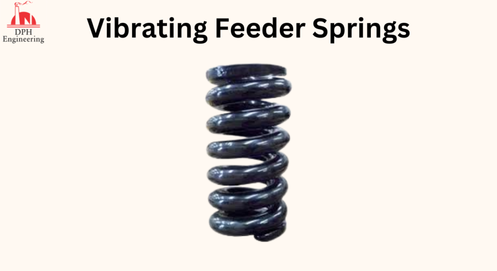
– Reactor Springs: These are the main springs that store and release energy while the vibrating system is working.
– Isolation Springs: These springs hold up the feeder and keep the structure that supports it from shaking because of the vibrations.
– Tuning Springs: These springs are used to change the frequency of a natural frequency feeder. This is done by adding or taking away springs or changing the rate of the springs. In other feeders, the frequency changes by adding or taking away weights.
– Dynamic Balancer: Balanced Vibratory feeders use a dynamic balancer to reduce the amount of dynamic force passed on to the structure that supports the feeder. This is done by responding to the forces of the drive unit as it turns around.
– Liner: Material added to the bottom of a trough to protect it from wear, heat, or cold, reduce noise and friction, or keep things from building up.
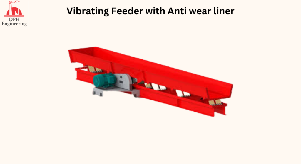
Screen: An extra part that helps separate fine particles from larger ones.
Grizzly: This is a heavy-duty screen made of bars, rails, or tubes that run in the direction of the flow of material. This is used to sort things that are bigger.
Vibratory feeders and conveyors have operating frequencies of 200 to 3600 vibrations per minute and amplitudes of 1 to 40 mm. Most of the time, the vertical acceleration is close to the acceleration of gravity (9.81 m/s2). This is enough to move things with a gentle shuffling motion that makes little noise and impact. Since this is the case, the material moves across the trough by sliding. When the pressure between the surface and the material is low, the material doesn’t actually leave the trough. When the material has to be lifted out of the trough and then hit again as it falls, special considerations must be made to deal with the impact force and the increased noise level.
Vibratory feeders are different from other equipment used to move bulk materials because the material moves separately from the medium that moves it. This is different from equipment like conveyor belts and aprons, where the material stays still while the medium moves it. This makes it possible to add more steps to the process while the material is in transit. Here are some things that can be done with vibratory feeders while transporting.
- Scalping
- Screening
- Sorting
- Spreading or Distributing
- Cooling
- Drying
- Dewatering
- Water Quenching
Vibratory feeders are wanted because, in addition to being able to add more processes,
Low Headroom is Needed: Vibratory feeders are the way to use gravimetric feeding in places where there isn’t much room up top. When moving bulk products horizontally, vibratory feeders are a good way to move them.
Handling Hot Materials Without Overheating: Vibratory feeders can be set up so that the up phases of the oscillation cycle create a little lift. This lets some air through to cool the material and keeps it from touching other things.
Handling Abrasive Materials: You can reduce vibration by adjusting the vibratory feeder so that it makes less contact with the material. Also, abrasion-resistant materials can be used to line the inside of vibratory feeders.
Built-in self-cleaning features: Since the material on the surface of the machine is not static, it doesn’t stick to it easily. There is no way for the stuff to pile up on the top of the trough.
Adherence to Strict Sanitation Requirements: A vibratory feeder has a pan or trough that is a continuous surface and also cleans itself. There are no cracks or holes where dirt could get stuck. The pan can be made out of stainless steel that can be used for food.
Water and Dust-Tight: Vibratory feeders can be designed with IP or NEMA-rated covers and sealing.
No Moving Parts Where Material Can Impinge and Interrupt Operation: Comparatively to belt and apron conveyors, the trough is a continuous tube without any joints, hinges, or deformable parts. These advantages make vibratory feeders popular in the mining, smelting, metal casting, recycling, batch processing of glass, furnace charging, wood processing, food processing, pharmaceuticals, and packaging industries.
Chapter 4: Types of Vibratory Feeders
Vibratory feeders can be put into different groups based on their drive unit, how the vibration is applied to the trough, and how the supporting structures react to the vibration. It is important to know the difference between these types when choosing a vibratory feeder. For example, just saying “brute force vibratory feeders” is not enough. There are both electromagnetic and electromechanical drive units for brute force feeders. This chapter talks about how each type works and what kinds of things you should use it for.
Vibratory Feeders by Drive Unit
Electromechanical Vibratory Feeders
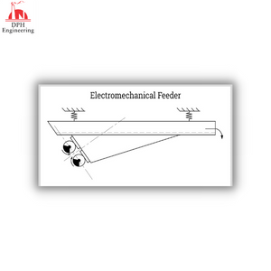
Electric motors turn eccentric weights inside these feeders, which makes them vibrate. They are also called mechanical feeders with eccentric mass. A simple design has only one mass that moves in an eccentric way. But using two masses that rotate in opposite directions is more common. The axes of rotation of these two masses are in the same plane, and their rotations are timed to make the right oscillation.
Electromagnetic Vibratory Feeders
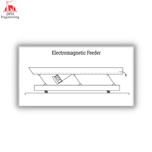
Electromagnetic feeders work by turning on and off one or more electromagnets in a cycle. Electromagnetic drive units have fewer moving parts than electromechanical drive units. The electromagnet sends magnetic force impulses that make the trough move back and forth. For low-volume applications, electromagnetic feeders are cheaper in terms of cost. When the rate is less than 5 tonnes per hour, this is true.
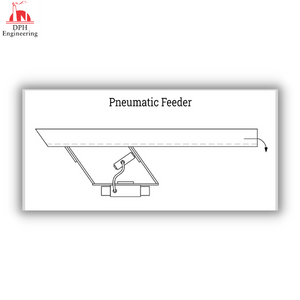
Hydraulic and Pneumatic Vibratory Feeders
These feeders use oscillating pistons that are powered by pneumatic or hydraulic systems. The primary benefit of adopting these types is that they are appropriate for dangerous regions. Remote locations may house the motors that operate the pumping units. This does away with the requirement for pricey explosion-proof standards.
Direct Vibratory Feeders:
Direct or positive mechanical vibratory feeders produce oscillations with a low frequency and a high amplitude using a crank and connecting rod. Due to the significant vibration that is transferred to the supporting structures, positive conveyors are rarely used. The use of a counterweight or counter-vibrating multiple troughs is two solutions for reducing the high vibration transmitted.
The many types of vibratory feeders are then listed in order of how the trough is vibrated. Their drive units’ frequency and amplitude, as well as the designs of their springs, are different.
Brute Force Feeders:
Due to the direct connection between the vibratory drive and the trough assembly, this form of feeder is known as a single-mass system. They typically work in heavy-duty situations. However, the electromechanical drive is the most common. The driving mechanism can also be electromagnetic. By rotating a large centrifugal counterweight, brute force feeders produce oscillating forces.
The design of the vibratory feeders is the most straightforward for brute-force feeders. However, because they are intended to be constant-rate feeders, they have a restricted range and feed rate regulation. By altering the trough’s slope, opening, amount of counterweight, and length of stroke, the feed rate can be changed. Since the trough stroke is only marginally dependent on the motor’s operating speed, variable speed drives are seldom fitted. In the case of brute force feeders, motor speed tuning is not required.
Centrifugal Feeders:
Centrifugal feeders, also referred to as rotary feeders, feature a revolving bowl that propels pieces outward. They have bowl walls enclosing a conical, centrally powered rotor. Rotational force separates parts and components as the feeder spins. The rotating components are pushed and dragged toward the bowl’s outside rim as they rotate quickly.
Centrifugal feeder systems are used in industries including food processing, pharmaceuticals, and medical supply that deal with small, oddly shaped parts that need to be handled quickly. Regardless of the size and shape of the components, centrifugal bowl feeders can sort and appropriately orient them at a pace of 3000 per minute. They are a low-maintenance, highly dependable, and cost-effective processing technology with a straightforward design.
Natural Frequency Feeder:
Natural frequency feeders employ two or more spring-connected masses and are also referred to as tuned or resonant feeders. The vibratory system with two masses and a spring connection is the most prevalent. Two masses are involved: one for the trough and the other for the response or excitation mass. The system operates at a speed that is close to its natural frequency or resonance condition, which results in a natural magnification of the oscillations that are used by the natural frequency feeder. As a result, the force needed to produce the desired vibratory forces is quite low. Rotating eccentric weights or electromagnets can produce vibratory force.
The damping capability of the bulk must be taken into account more than the weight of the material or load. The material’s ability to absorb energy produces the damping effect. When vibrated, granular and powdered materials have a tendency to lose energy through intergranular friction and deformation.
According to how they respond to the supporting structures and foundations, vibratory feeders are likewise divided into several categories. The rigidity and permissible stresses of the structure must be considered while choosing the type.
Unbalanced Vibratory Feeders:
These feeders feature fluctuating forces that put reverse load situations on the supporting structures. Continuous and alternating tensile and compressive forces with zero mean stress are referred to as reversing load conditions. Despite being able to withstand the feeder’s static load with ease, the supporting structure becomes readily worn down when in use. Only structures with very wide permissible deflections in relation to the amplitude of the vibrations can support the installation of unbalanced vibratory feeders. Additionally, the structure’s inherent frequency must be far higher than the feeder’s working frequency.
Balanced Vibratory Feeders:
A dynamic balancing mechanism made up of counterbalancing weights fitted on the conveyor base is included with a balanced vibratory feeder. In some systems, the reactor springs are coupled with secondary weights. These feeders are made with the intention of minimizing the unbalanced response force that is delivered to the supporting structure. The secondary weights are vibrated 180 degrees out of phase with the oscillation of the trough to accomplish this. When installing vibratory feeders on structures whose rigidity is in doubt, balanced vibratory feeders are advised.
Horizontal Motion Conveyors
Horizontal motion conveyors often referred to as differential motion conveyors, horizontal differential conveyors, or differential conveyors, are used to move free-flowing bulk materials horizontally using a two-cycle slow advance, swift return motion. The conveying surface is a slow-moving open pan or closed conduit that is made of a single seamless piece. Components stay at calm rest while moving ahead. The components are deposited during the return cycle as the open pan or closed conduit moves quickly and quickly backward.
Materials are smoothly conveyed at a rate of 40 feet (12 meters) per minute over distances of up to 200 feet using a horizontal motion conveyor that continuously alternates between forward and backward motion (61 m). Other than the drive unit, they don’t have any moving components, which lowers safety hazards, makes cleaning easier and requires less maintenance. Horizontal motion conveyors are perfect for handling delicate products because of their smooth, even motion.
Components can be moved backward or forward on horizontal motion conveyors one direction at a time. For flat rectangular or square sections, they can be set up to operate on very modest declines or inclinations. To transport parts in the middle, horizontal motion conveyors can be built up if necessary. The components do not experience vertical acceleration or bouncing as they move down the open pan or conduit.
Chapter 5: Feeder Trough Design
The capacity of the vibrating feeder depends on the width of the trough, depth of material flow, bulk density of the material, and the linear feed rate. This is expressed by the formula,
C = WdR / 4800
Where C is the capacity in tons per hour (metric tons per hour), W is the trough width in inches (millimeter), d is the depth of material in inches (millimeter), γ is the bulk density in pounds per cubic feet (grams per cubic centimeter), and R is the linear feed rate in feet per minute (meter per minute). For metric units, change the 4,800 constant to 16,700.
Typically, the rate requirements of upstream or downstream operations already provide the necessary capacity. Combinations of trough width, linear feed rate, material bulk density, and anticipated feed depth can be calculated from the needed capacity. The properties of the feeder are often described in charts, tables, and graphs by the manufacturer.
Stainless steel grade 304, mild steel, and abrasion-resistant alloys are frequently used to create feeder troughs. Other buildings are made of regular steel that is lined with changeable rubber, plastic, or ceramic materials. Depending on the kind of material used, its characteristics, and the combined operations, troughs can take on a variety of shapes. Typical trough shapes and characteristics include:
- Flat Bottom
- Half Round Bottom
- Radius Bottom
- V Shape
- Tubular
- Grizzly Section
- Dust and water-tight sealing and cover
- Belt-centering Discharge
- Diagonal Discharge
- Screen Decks
- Water-jacketed
Chapter 6: Vibratory Bowl Feeders
Vibratory bowl feeders have troughs that are wrapped helical, and they employ vibrations to toss and shuffle materials around the surface of the helical trough, which is slightly tilted. Parts with asymmetrical forms are aligned as they pass through the bowl feeder thanks to the tossing and shuffling movements.
A vibrating bowl feeder has the advantage of conveying pieces and arranging them correctly. To accept materials in the right orientation, troughs have certain profiles. Parts that are not aligned or positioned properly are removed by screening equipment attached to the bowl. In the electronics, automotive, and pharmaceutical industries, vibratory bowl feeders are utilized in assembly and packaging lines.
Conclusion:
– Vibratory feeders are small conveyors that move bulk materials with the help of gravity and a regulated vibratory force mechanism. The materials being handled experience a combination of horizontal and vertical acceleration from the vibrations through tossing, hopping, or sliding motion.
Dry solids in the form of powder, granules, or particles of varying sizes and densities are referred to as bulk materials. They do not move as reliably and easily as liquids and gases do.
– A deep channel, or trough, which holds the bulk material, and a driving unit that produces the vibratory action make up the basic structure of a vibratory feeder.
– The drive unit, a technique used to apply vibration to the trough, and the resultant reaction to the supporting structures can all be used to classify vibratory feeders.
Vibratory bowl feeders are unique varieties of vibratory feeders with troughs twisted helically with specialized attachments and profiles. They are employed in applications involving partial or item feeding where the objects must be in a particular orientation.
Contact us for more details!
DPH Engineering is regarded as one of India’s top suppliers of industrial machinery. Modern production tools and excellent service have been provided to our clients even after the sale has been completed. We can provide you with the manufacturing-related answers you require in the real world as well as experienced advice. If you’re considering installing conveyor belts to increase the productivity of your assembly line, don’t hesitate to contact us.
Are you considering incorporating conveyor belts into your manufacturing process? A reputable business selling packing equipment and related extras like conveyor belts is DPH Engineering. They have attained these honors by being masters at creating, producing, repairing, setting up, and installing this machinery. Since its founding, DPH Engineering has focused on the requirements for material handling equipment.

