Frequency Controller Fq2ng
Introduction

METALLIC BOX
PV R4FC Z2 STM 140x115x60

METALLIC BOX
PV R4FC Z2 STM 140x115x60

CIRCUIT
PV R4FC A2 STD
WARNINGS
Before using the appliance it is necessary to read attentively the instructions included in this technical sheet which provides you information about safety installation, use and maintenance. keep this sheet safely for further future information.
GENERAL INSTRUCTIONS
Before connecting the equipment to the mains socket, make sure that the nameplate data matches with those of the mains power supply. Only use this equipment in accordance with the purpose of its design and manufacture; i.e. for the regolation of the amplitude and frequency of an electromagnetic vibrator feeder. Any other use it is an improper use or even hazardous. The Manufacturer cannot (is not) be considered liable for any improper, incorrect or unreasonable use of the equipment. In the event of malfunctioning switch it off and do not tamper with it. For any repairs, please contact the Manufacturer’s Technical Service Centre only, as they use original spare parts. Failure to comply with those recommendations could affect the safety of the equipment. All operations regarding adjustment, measurement and testing when required, must only be carried out by authorized and qualified personnel. The Manufacturer shall accept no liability for damage to persons, animals or objects caused by equipment’s works carried out by unauthorized and unqualified personnel.
This equipment conforms with ecc directive 2014/30/UE
(EMC- Electromagnetic Compatibility)
and directive 2014/35/UE (LVD – Low Voltage Directive)
GENERAL INFORMATION
The digital Controller FQ2NG has been designed in order to optimise the operation of vibrators by varying the frequency and the vibration amplitude, using or not using an amplitude sensor SIND3 (optional), to be controlled by a PLC signal of 0/10V (4/20mA). Furthermore, the possibility to adjust the frequency allows to compensate all those slipping phenomena due to the variation of the system’s mechanical characteristics, to the different materials and to the temperature. This allows the best performances in all situation. Furthermore, there is a signal ON-status which is able to control an overflow sensor PNP and other PNP sensor (delay 4/20 sec.) Its versatility makes the device very suitable for all application, where dimensions and weight of the handled parts handled are subject to frequent changes. The regulation circuits are galvanically insulated from the power section. The controller is able to supply a tension of 200 V at a maximum current of 6 Amps and a ramp (0/5 sec.) start-up, provided with a user-friendly menu. The regulation system is based on a microprocessor and allows a wide linear control-range (5/140 Hz) (5/300 Hz on request). The system can operate with a SIND3 amplitude-sensor in order to compensate the vibrator’s load changes or the Blow / air (delayed), time missing pieces flow (0-240 sec.) with relative alarm (24Vdc). The input password (for avoid unauthorized adjustments), complete the FQ2NDIG functions.
PARTICULAR INSTRUCTIONS
Switching on the control appear the number software version. To enter in menu press key.
After 30 sec., the system returns to the display of the operation mode. Therefore at anytime the display will show the fre- quency entered and the percentage of power supplied for the loading to use .
TECHNICAL CHARACTERISTICS
| SUPPLY VOLTAGE: 230V (115V) +/- 5% 50/60Hz | TIME ALARM: 0/240 sec. |
| CONSUMPTION: 1 W max | LAMP ALARM: 24 V – no flow pieces- Product Missing |
| CURRENT MAX VIB.: 6A RMS | REGULATION WITH POTENTIOMETER: see note |
| FUSE: 6A F 250V 5×20 H 1500A (F1-F2-F3) | TIME RAMP: 0/5 sec. |
| LOAD MIN: 50mA | AMPLITUDE SENSOR: SIND3 on request |
| REG. MIN/MAX.: 0/100% | INPUT ON/OFF: free voltage – contact signal voltage 0/24 V |
| AUTOMATIC INPUT : 0/10V – 4/20mA (with 470 Ohm) | DEGREE OF PROTECTION: IP55 |
| REG. FREQUENCY: 5/140 Hz (5/200 Hz)-(5/300 Hz) | TEMPERATURE OF STORAGE: -20 °C / + 80 °C |
| SENSOR INPUT: PNP 24 Vdc (delay 0/20 sec.) | TEMPERATURE OF OPERATION: -10 °C / + 45 °C |
| BLOW AIR: 24 Vcc – delay 0-60 sec. | RANGE OF RELATIVE HUMIDITY: 80% TILL TO 31°C |
| OUTPUT STATUS SIGNAL: 24 V – RELAY CONTACT | WARANTY: 1 YEAR. |
| Code: MUMFQ2NG | Rev.: 00 | Edit: E. Pedrazzi | Date: 01/20 | Sheet : 2 |

WHAT TO DO IN THE FOLLOWING CASES – MESSAGE DISPLAY
| THE DISPLAY AND THE MAIN SWITCH REMAIN OFF | Make sure that the 110 ÷230V powering line is running |
| THE DISPLAY IS OFF BUT THE MAIN SWITCH IS ON | Check the F1/F2 fuse – check max current on vibrator Make sure that the flat cable has been introduced into the connector correctly |
| THE DISPLAY IS OFF BUT THE MAIN SWITCH IS ON | Check the programming of the inverter as for its “FC1” function If no external PNP sensor is used, the “not required” status must be selected. impostazioni menù 1.1 (feeder out = enable) menù 4.2 Select Keyboard – if manual menù 4.1 change enable logic |
MESSAGE DISPLAY
| TIMEOUT | Timeout enable (menù 2.5). If enable stops the feeder for alarm absence pieces |
| PRODUCT MISSING | Alarm absence pieces |
| DISABLED | Enable set on OFF (MENÙ 1.1) |
| STOP | Stop output feeder (red key 0 ) |
| fuLL | Vibrator full off vibrator (flash fuLL: time ON Vibrator) |
| oFF | Enable consent |
| ON | ON vibratore (flash ON: time OFF Vibratore) |
| sensor error | Without sensor SIND3 (just for the version that supports it code PVFQ2NGZ2STD) |
IF AFTER THESE CHECKS THE FQ2NG DOES NOT RUN, PLEASE SEND IT BACK TO THE MANUFACTURE IN ORDER TO REPAIR IT.
| NOTE : Do not use the apparatus in proximity of subject zones to vibrations (use anti-vibrating support), or in acid and humid working environment. |
| Code: MUMFQ2NG | Rev.: 00 | Edit: E. Pedrazzi | Date: 01/20 | Sheet : 3 |

CONTROLLER FQ2SG
The control system consists of an electronic circuit FQ2SG that processes signals, an amplitude sensor SIND3 as accelerometer control signal transducer, specifically the amplitude, and a vibrator that needs to be checked.
Working with accelerometer SIND3 you must install appropriately the acceleration sensor on magnetic vibrator, the system with FEEDBACK can’t work if the SIND3 sensor is not connected.
The SIND3 sensor, that must be mounted in an area where it can “feel” the vibration, provides in real time to the circuit a voltage value proportional to the measured amplitude and the circuit compares the chosen operating point to this return signal, keeping it in balance.
If a change occurs, and the SIND3 sensor recognizes a displacement of this work-point compared to the point set by the user, the FQ2SG circuit shows quickly the proportional voltage of the sensor to a value close to the point set by the user.
The point where the SIND3 sensor is set, will be the reference point to stabilize.
The following considerations related to the optimum working condition are:
If the circuit is optimized with an empty vibrator, then the working point must be set adequately below the line voltage, so that, once weighted down with the load, the circuit can keep the vibration stable supplying a higher exit voltage. If the optimasation is carried out with a fully loaded vibrator, then the voltage on the vibrator could reduce as channel or bucket empties out. This is why the working point can be fixed close to the line voltage
CONTROLLER FQ2SG
 The digital controller FQ2SG uses a PWM signal (Pulse Wide Modulation) to produce a sinusoidal wave that is adjustable in both amplitude
and frequency. With frequency adjustment, it is possible to optimize the vibrator’s function and use the same feeder supplied by AC mains
at either 50Hz or 60Hz.
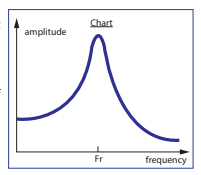
Resonant frequency: Resonant frequency is defined as the point where the controller operates at maximum amplitude whilst consuming current most efficiently. The difference of a few Hz from the resonant frequency can reduce the efficiency of the vibrator, thereby wasting more power.
The vibrator works optimally at a value close to its resonant frequency (+/-1 or 2 Hz).
A digital controller with frequency control will electronically locate the resonant frequency of
the vibrator which would otherwise require the manual adjustment of the vibrator by eye, using a
controller with fixed frequencies of 50 Hz or 100 Hz.
Because of the many elements of a vibrator, two identical vibrators can have slightly different amplitudes
when operating at the same power. This is due to small random manufacturing imperfections, for this
reason every vibrator typically needs to be adjusted manually to operate at the resonant frequency.
Caution: It should be noted that at low operating frequencies, the current consumption increases, thereby warming the vibrator. Please ensure that the magnet used in the feeder’s operates within its limits and that it is sized correctly for the operating frequency setting.
Caution: When measuring a PWM signal you must use an appropriate instrument that ensures reliable measure that does not produce
systematic error.