Electromechanical Feeder
Syntron Electromechanical Feeder Supplier & Manufacturer In India.
Introduction
Let DPH Engineering’s knowledgeable team help your business with conveying, feeding, screening, elevating, vibratory flow aids, and mining controls of bulk products. Whether optimizing existing systems or starting from the ground-up on new and customized plants or mines, our dedicated staff will provide you with the most efficient and cost-effective solutions.
An international leader for innovative solutions, DPH Engineering can improve the technology customers are already using. The Link-Belt expertise and equipment have been instrumental in developing some of the world’s largest belt conveyors. The Syntron feeders are instrumental to supplying energy sources and material handling efforts across the globe. DPH Engineering is committed to the success and growth of our company by investing in engineering capabilities, manufacturing efficiency and our world class customer service. Our dedicated employees and industry leading engineered products make us a market leader.
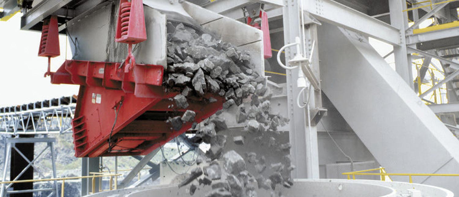
DPH Engineering MF Heavy-Duty Electromechanical Feeder is the heavy-weights of bulk material handling and is used for higher capacity requirements. The eight heavy-duty models handle capacities from 100 to 4,000 tons per hour. Syntron Heavy-Duty Electromechanical Feeders combine extra structural strength with durable components. The deep wing plates form a bridge between the inlet and discharge suspension supports, providing extra strength for years of dependable service. Standard troughs feature unitized weldments—a one-piece, completely welded units for greater strength. Troughs are also available with bolt-together construction for tunnel installations or other confined areas. MF Heavy-Duty Electromechanical Feeder is two-mass, spring-connected and sub-resonant-tuned. The exciter unit is connected to the trough with corrosion resistant polymeric drive springs, which reduces the stroke vertically while amplifying stroke in the direction of material flow. This feature creates straight-line motion providing maximum material flow rate and feeder capacity. Syntron feeders also utilize custom-engineered Electromechanical Vibrators. These vibrators feature an L10 life expectancy averaging over 100,000 hours in normal operations and they allow for quick removal via access from both sides of the feeder or out the bottom. Attachments for safety cables are included on all DPH Engineering feeders.
MF Electromechanical Direct Drive Feeder Features
- Operating frequency – 1100 VPM at 55.4 Hz
- Stroke: 0.25 – 0.36 inches
- Dependable, flexible, easily adjustable
- Minimal component design to reduce adjustments and replacements due to wear • Quick replacement of Drive Unit
- Infinite unbalance adjustment
- VFD control providing 10:1 turn-down feed adjustment
- Sub-resonant tuning
- Stroke consistency and speed stability under varying headload and material dampening
- Start and operate fully loaded or empty
- Structural strength
- Deep wing plates
- Engineered weldments using the latest FEA techniques and software
- Hazardous Area Service
- Explosion proof motors
- ULXP: Class 1, Div 1, Group C & D Class 2, Div 1, Group E & F
- Bolt-in trough liners
- T1-A • AR-400, AR-500
- 304 stainless steel
- Chromium carbide overlay ceramic
- UHMW, TIVAR, rubber
DPH Engineering Electromechanical Feeder Features
- Operating frequency – 1100 VPM at 60Hz
- Stroke: 0.25 – 0.36 inches
- Start and operate in an empty or fully-loaded state
- Dependable, flexible, easily adjustable control
- Precise sub-resonant tuning ratio
- Stroke consistency and speed stability under varying material conditions
- Reduces the effects of varying headload and material damping
- Structural strength
- Deep wing plates
- Unitized weldments
- Infinite unbalance adjustment
- Achieve the desired stroke with easy adjustment
- Suitable for use in hazardous areas
- Explosion-proof motors required by coal, coke or other hazardous environments are available
- Bolt-in trough liners
- Based on dry sand weighing 100 pounds per cubic foot. Capacities vary depending on material characteristics, material density, trough length and width, trough liner type, feeder installation, skirt boards, and hopper transitions.
Service and Support
At DPH Engineering, we understand that good, reliable equipment—operating at peak performance—is crucial to your bottom line. That’s why we’re committed to giving our customers value—before, during, and after the sale. DPH Engineering is based on the most rugged, reliable, and durable vibratory equipment available – Syntron vibrating feeders, conveyors, screens, and bin vibrators. To begin with, we’ll help you select the right equipment, considering all the variables of your application in order to maximize production and reduce costs. Once you’re up and running, our Services Team will keep you on top and moving ahead. We’re on call – at the factory or in the field – wherever and whenever you need us for parts, service, inspection and training. Dependable equipment is critical to your operation, and your success is critical to our success. AtDPH Engineering, your satisfaction is our number one priority. You can rely on us.
Electromagnetic Feeder Specifications
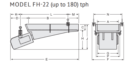
Based on feeder with 10˚ down slope, below-deck drive unit, installed with proper hopper transition and skirt board arrangement, feeding sand weighing 100 pounds per cubic foot. 240/480/600 Volt 60 Hz single-phase. 230/400/415 Volt 50 Hz single-phase. Above-deck and base mounting drive units are available
|
Approx. Trough W x L |
Approx. Capacity tph ◆ |
Approx. Current (460V) |
Control Model |
Net Wt. (lb) |
Net Wt. (kg) |
Approx. Ship Wt. (lbs) Feeder/ Control | Approx. Ship Wt. (kg) Feeder/ Control |
| 12 x 60 | 50 | 5 amps | EVF-7.5D | 480 | 217 | 575 | 260 |
| 18 x 42 | 125 | 5 amps | EVF-7.5D | 46 0 | 208 | 555 | 251 |
| 24 x 42 | 180 | 5 amps | EVF-7.5D | 480 | 217 | 575 | 260 |
| A | B | C | D | E | F | G | H | J | K | L | M | N | P | |
| in mm | 12
305 |
60
1524 |
5
127 |
6 1/2
165 |
66 1/2
1689 |
23
584 |
17 1/2
445 |
16 1/2
419 |
21 1/2
546 |
8 1/4
210 |
47 3/4
1213 |
10 1/2
267 |
18 3/4
476 |
19 3/4
502 |
| in mm | 18
457 |
42
1067 |
5
127 |
15 5/16
389 |
57 5/16
1456 |
26 3/4
679 |
17 1/2
445 |
18
457 |
23
584 |
8 5/16
211 |
40
1016 |
9
229 |
24 3/4
629 |
19 3/4
502 |
| in mm | 24
610 |
42
1067 |
5
127 |
15 5/16
389 |
57 5/16
1456 |
32 3/4
832 |
17 1/2
445 |
18
457 |
23
584 |
8 5/16
211 |
40
1016 |
9
229 |
30 3/4
781 |
19 3/4
502 |
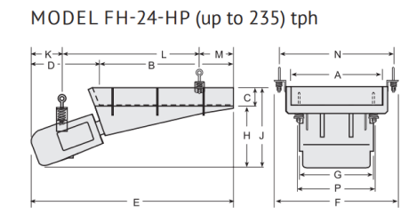
Based on feeder with 10˚ down slope, below-deck drive unit, installed with proper hopper transition and skirt board arrangement, feeding sand weighing 100 pounds per cubic foot. 240/480/600 Volt 60 Hz single-phase. 230/400/415 Volt 50 Hz single-phase. Above-deck and base mounting drive units are available.
|
Approx. Trough W x L |
Approx. Capacity tph ◆ |
Approx. Current (460V) |
Control Model |
Net Wt. (lb) |
Net Wt. (kg) |
Approx. Ship Wt. (lbs) Feeder/ Control | Approx. Ship Wt. (kg) Feeder/ Control |
| 18 x 60 | 125 | 7 amps | EVF-7.5D | 600 | 272 | 650 | 294 |
| 24 x 48 | 235 | 7 amps | EVF-7.5D | 600 | 272 | 650 | 294 |
| 30 x 36 | 200 | 7 amps | EVF-7.5D | 600 | 272 | 650 | 294 |
| A | B | C | D | E | F | G | H | J | K | L | M | N | P | |
| in mm | 18
457 |
60
1524 |
5
127 |
6 5/16
160 |
66 5/16
1684 |
28
711 |
19 5/8
498 |
18
457 |
23
584 |
8 5/16
211 |
47 1/2
1207 |
10 1/2
267 |
24 3/4
629 |
24 3/4
629 |
| in mm | 24
610 |
48
1219 |
5
127 |
12 5/16
313 |
60 5/16
1532 |
32 3/4
832 |
19 1/4
489 |
18
457 |
23
584 |
8 5/16
211 |
41 7/8
1064 |
10 1/8
257 |
30 3/4
781 |
19 3/4
502 |
| in mm | 30
762 |
36
914 |
5
127 |
8 5/16
135 |
54 5/16
1380 |
38 3/4
984 |
19 1/4
489 |
18
457 |
23
584 |
8 5/16
211 |
37
940 |
9
229 |
36 3/4
933 |
19 3/4
502 |
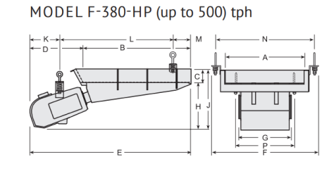
Based on feeder with 10˚ down slope, below-deck drive unit, installed with proper hopper transition and skirt board arrangement, feeding sand weighing 100 pounds per cubic foot. 240/480/600 Volt 60 Hz single-phase. 230/400/415 Volt 50 Hz single-phase. Above-deck and base mounting drive units are available.
|
Approx. Trough W x L |
Approx. Capacity tph ◆ |
Approx. Current (460V) |
Control Model |
Net Wt. (lb) |
Net Wt. (kg) |
Approx. Ship Wt. (lbs) Feeder/ Control | Approx. Ship Wt. (kg) Feeder/ Control |
| 24 x 60 | 250 | 18 amps | EVF-15D | 1370 | 621 | 1400 | 635 |
| 30 x 60 | 500 | 18 amps | EVF-15D | 1400 | 635 | 1450 | 657 |
| 36 x 48 | 500 | 18 amps | EVF-15D | 1400 | 635 | 1450 | 657 |
| A | B | C | D | E | F | G | H | J | K | L | M | N | P | |
| in mm | 24
610 |
60
1524 |
6
152 |
18 1/8
460 |
78 1/8
1984 |
35 7/8
911 |
23 1/4
591 |
22 3/4
578 |
28 3/4
730 |
12 7/8
327 |
50 3/4
1289 |
14 1/2
368 |
32 5/8
829 |
32
813 |
| in mm | 30
762 |
60
1524 |
6
152 |
18 1/8
460 |
78 1/8
1984 |
41 7/8
1064 |
23 1/4
591 |
22 3/4
578 |
28 3/4
730 |
12 7/8
327 |
50 3/4
1289 |
14 1/2
368 |
38 5/8
981 |
36
91 |
| in mm | 36
914 |
48
1219 |
6
152 |
24 1/8
613 |
72 1/8
1832 |
47 7/8
1016 |
23 1/4
591 |
22 3/4
578 |
28 3/4
730 |
12 7/8
327 |
50 3/4
1289 |
8 1/2
216 |
44 5/8
1133 |
26 1/4
666 |
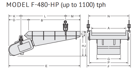
Based on feeder with 10˚ down slope, below-deck drive unit, installed with proper hopper transition and skirt board arrangement, feeding sand weighing 100 pounds per cubic foot. 480/600 Volt 60 Hz single-phase. 400/415 Volt 50 Hz single-phase. Above-deck and base mounting drive units are available.
|
Approx. Trough W x L |
Approx. Capacity tph ◆ |
Approx. Current (460V) |
Control Model |
Net Wt. (lb) |
Net Wt. (kg) |
Approx. Ship Wt. (lbs) Feeder/ Control | Approx. Ship Wt. (kg) Feeder/ Control |
| 42 x 84 | 1100 | 31.5 amps | EVF-25D | 4100 | 1859 | 4200 | 1905 |
| 48 x 72 | 1100 | 31.5 amps | EVF-25D | 4000 | 1814 | 4100 | 1859 |
| A | B | C | D | E | F | G | H | J | K | L | M | N | P | |
| in mm | 42
1067 |
84
2134 |
7
178 |
23 15/16
608 |
107 15/16
2742 |
54 3/8
1381 |
33
838 |
30 11/16
779 |
37 11/16
957 |
17 7/16
443 |
71 1/2
1816 |
19
483 |
50 3/4
1289 |
51
1295 |
| in mm | 48
1219 |
72
1829 |
7
178 |
28 1/16
713 |
100 1/16
2542 |
60 3/8
1534 |
33
838 |
27 13/16
706 |
34 13/16
884 |
17 1/2
445 |
61 5/8
1565 |
21
533 |
56 3/4
1441 |
57
1448 |
Electromagnetic Feeder Specifications
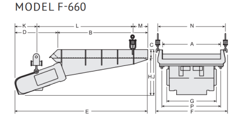
Based on feeder with 10˚ down slope, below-deck drive unit, installed with proper hopper transition and skirt board arrangement, feeding sand weighing 100 pounds per cubic foot. 480/600 Volt 60 Hz single-phase. 400/415 Volt 50 Hz single-phase. Above-deck and base mounting drive units are available.
|
Approx. Trough W x L |
Approx. Capacity tph ◆ |
Approx. Current (460V) |
Control Model |
Net Wt. (lb) |
Net Wt. (kg) |
Approx. Ship Wt. (lbs) Feeder/ Control | Approx. Ship Wt. (kg) Feeder/ Control |
|
60 x 90 |
1000 |
31.5 amps |
EVF-25D |
9200 |
4173 |
9300 |
4218 |
| A | B | C | D | E | F | G | H | J | K | L | M | N | P | |
| in mm | 60
1524 |
90
2286 |
8
203 |
40
1016 |
130
3302 |
72 1/2
1842 |
51 1/2
1308 |
39 1/2
1003 |
47 1/2
1207 |
21 1/2
546 |
96
2438 |
15 1/2
394 |
69
1753 |
63 1/2
1613 |
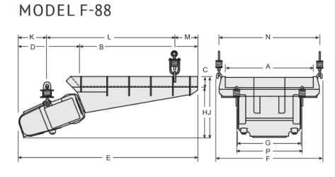
Based on feeder with 10˚ down slope, below-deck drive unit, installed with proper hopper transition and skirt board arrangement, feeding sand weighing 100 pounds per cubic foot. 480/600 Volt 60 Hz single-phase. 400/415 Volt 50 Hz single-phase. Above-deck and base mounting drive units are available.
|
Approx. Trough W x L |
Approx. Capacity tph ◆ |
Approx. Current (460V) |
Control Model |
Net Wt. (lb) |
Net Wt. (kg) |
Approx. Ship Wt. (lbs) Feeder/ Control | Approx. Ship Wt. (kg) Feeder/ Control |
|
72 x 96 |
1600 |
70 amps |
EVF-60D |
11400 |
5170 |
12000 |
5443 |
| A | B | C | D | E | F | G | H | J | K | L | M | N | P | |
| in mm | 72
1829 |
96
2438 |
8
203 |
49 9/16
1259 |
145 9/16
3697 |
87
2210 |
51 1/2
1308 |
40 3/32
1018 |
48 3/32
1222 |
22 3/4
578 |
103 9/16
2630 |
19 1/4
489 |
82
2083 |
63 1/2
1613 |
Related Products:
